Geometry and Appearances
This is a draft for a three-part blog series. The first two are Cesium tutorials. The last is a general graphics tech article.
Cesium has a library of primitives, such as polygons and ellipsoids, that are the visual building blocks of our scene. To use them, we create a primitive with position data and perhaps a material. For example, copy and paste the following into the Hello World Sandcastle Example to create an extent on the globe with a dot pattern:
var widget = new Cesium.CesiumWidget('cesiumContainer');
var scene = widget.scene;

scene.getPrimitives().add(new Cesium.ExtentPrimitive({
    extent : Cesium.Extent.fromDegrees(-100.0, 20.0, -90.0, 30.0),
    material : Cesium.Material.fromType(scene.getContext(), 'Dot')
})); 
In this tutorial, we go under the hood of primitives and look at the Geometry and Appearance types that form them. A geometry defines the primitive's structure, i.e., the triangles, lines, or points that compose the primitive. An appearance defines the primitive's shading, including its full GLSL vertex and fragment shaders, and render state.
Cesium supports the following geometries.
 |
BoxGeometry |
 |
BoxOutlineGeometry |
A box. |
 |
CircleGeometry |
 |
CircleOutlineGeometry |
A circle or extruded circle |
 |
CorridorGeometry |
 |
CorridorOutlineGeometry |
A polyline normal to the surface with a width in meters and optional extruded height. |
 |
CylinderGeometry |
 |
CylinderOutlineGeometry |
A cylinder, cone, or truncated cone. |
 |
EllipseGeometry |
 |
EllipseOutlineGeometry |
An ellipse or extruded ellipse. |
 |
EllipsoidGeometry |
 |
EllipsoidOutlineGeometry |
An ellipsoid. |
 |
ExtentGeometry |
 |
ExtentOutlineGeometry |
An rectangle or extrdued rectangle. |
 |
PolygonGeometry |
 |
PolygonOutlineGeometry |
A polygon with optional holes or extruded polygon. |
 |
PolylineGeometry |
 |
SimplePolylineGeometry |
A collection of line segments with a width in pixels. |
 |
SphereGeometry |
 |
SphereOutlineGeometry |
A sphere. |
 |
WallGeometry |
 |
WallOutlineGeometry |
A wall perpendicular to the globe. |

The benefits of using geometries and appearances are:
- Performance - When drawing a large number of static primitives (such as polygon for each zip code in the United States), using geometries directly allows us to combine them into a single geometry to reduce CPU overhead and better utilize the GPU. Combining primitives is done on a web worker to keep the UI responsive.
- Flexibility - Primitives combine geometry and appearance. By decoupling them, we can modify each independently. We can add new geometries that are compatible with many different appearances and vice-versa.
-
Low-level access - Appearances provide close-to-the-metal access to rendering without having to worry about all the details of using the
Rendererdirectly. Appearances make it easy to:- Write full GLSL vertex and fragment shaders.
- Use custom render state.
There are also some downsides:
- Using geometries and appearances directly requires more code and a deeper understanding of graphics. Primitives are at the level of abstraction appropriate for mapping apps; geometries and appearances have a level of abstraction closer to a traditional 3D engine.
- Combining geometries is effective for static data, not necessarily for dynamic data.
Let's rewrite the initial code example using geometries and appearances:
var widget = new Cesium.CesiumWidget('cesiumContainer');
var scene = widget.scene;

// original code
// scene.getPrimitives().add(new Cesium.ExtentPrimitive({
//     extent : Cesium.Extent.fromDegrees(-100.0, 20.0, -90.0, 30.0),
//     material : Cesium.Material.fromType(scene.getContext(), 'Dot')
// }));

var instance = new Cesium.GeometryInstance({
  geometry : new Cesium.ExtentGeometry({
    extent : Cesium.Extent.fromDegrees(-100.0, 20.0, -90.0, 30.0),
    vertexFormat : Cesium.EllipsoidSurfaceAppearance.VERTEX_FORMAT
  })
});

scene.getPrimitives().add(new Cesium.Primitive({
  geometryInstances : instance,
  appearance : new Cesium.EllipsoidSurfaceAppearance({
    material : Cesium.Material.fromType(scene.getContext(), 'Dot')
  })
}));
Instead of using the explicit ExtentPrimitive type, we used the generic Primitive, which combines the geometry instance and appearance. For now, we will not differentiate between a Geometry and a GeometryInstance other than an instance is a container for a geometry.
To create the geometry for the extent, i.e., the triangles covering the rectangular region and that fit the curvature of the globe, we create an ExtentGeometry.

Since we know it is on the surface, we can use the EllipsoidSurfaceAppearance. This is able to save memory and support all materials given that the geometry is on the surface or at a constant height above the ellipsoid.
We see a performance benefit when we use one primitive to draw multiple static geometries. For example, let's draw two rectangles.
var widget = new Cesium.CesiumWidget('cesiumContainer');
var scene = widget.scene;

var instance = new Cesium.GeometryInstance({
  geometry : new Cesium.ExtentGeometry({
    extent : Cesium.Extent.fromDegrees(-100.0, 20.0, -90.0, 30.0),
    vertexFormat : Cesium.EllipsoidSurfaceAppearance.VERTEX_FORMAT
  })
});

var anotherInstance = new Cesium.GeometryInstance({
  geometry : new Cesium.ExtentGeometry({
    extent : Cesium.Extent.fromDegrees(-85.0, 20.0, -75.0, 30.0),
    vertexFormat : Cesium.EllipsoidSurfaceAppearance.VERTEX_FORMAT
  })
});

scene.getPrimitives().add(new Cesium.Primitive({
  geometryInstances : [instance, anotherInstance],
  appearance : new Cesium.EllipsoidSurfaceAppearance({
    material : Cesium.Material.fromType(scene.getContext(), 'Dot')
  })
})); 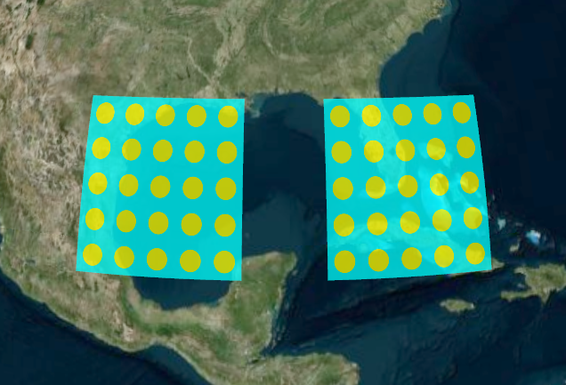
We created another instance with a different extent, and then provided both instances to the primitive. This draws both both instances with the same appearance.
Some appearances allow each instance to provide unique attributes. For example, we can use PerInstanceColorAppearance, to shade each instance with a different color.
var widget = new Cesium.CesiumWidget('cesiumContainer');
var scene = widget.scene;

var instance = new Cesium.GeometryInstance({
  geometry : new Cesium.ExtentGeometry({
    extent : Cesium.Extent.fromDegrees(-100.0, 20.0, -90.0, 30.0),
    vertexFormat : Cesium.PerInstanceColorAppearance.VERTEX_FORMAT
  }),
  attributes : {
    color : new Cesium.ColorGeometryInstanceAttribute(0.0, 0.0, 1.0, 0.8)
  }
});

var anotherInstance = new Cesium.GeometryInstance({
  geometry : new Cesium.ExtentGeometry({
    extent : Cesium.Extent.fromDegrees(-85.0, 20.0, -75.0, 30.0),
    vertexFormat : Cesium.PerInstanceColorAppearance.VERTEX_FORMAT
  }),
  attributes : {
    color : new Cesium.ColorGeometryInstanceAttribute(1.0, 0.0, 0.0, 0.8)
  }
});

scene.getPrimitives().add(new Cesium.Primitive({
  geometryInstances : [instance, anotherInstance],
  appearance : new Cesium.PerInstanceColorAppearance()
})); 
Each instance has a Color attribute. The primitive is then constructed with a PerInstanceColorAppearance, which knows to use each instance's color attribute to determine shading.
Combining geometries allows Cesium to efficiently draw A LOT of geometries. The following example draws 2,592 uniquely colored rectangles. It will take a second or two to optimize the geometry, then drawing is very fast.
var widget = new Cesium.CesiumWidget('cesiumContainer');
var scene = widget.scene;

var instances = [];

for (var lon = -180.0; lon < 180.0; lon += 5.0) {
  for (var lat = -90.0; lat < 90.0; lat += 5.0) {
    instances.push(new Cesium.GeometryInstance({
      geometry : new Cesium.ExtentGeometry({
        extent : Cesium.Extent.fromDegrees(lon, lat, lon + 5.0, lat + 5.0)
      }),
      attributes : {
        color : Cesium.ColorGeometryInstanceAttribute.fromColor(Cesium.Color.fromRandom({alpha : 0.5}))
      }
    }));
  }
}

scene.getPrimitives().add(new Cesium.Primitive({
  geometryInstances : instances,
  appearance : new Cesium.PerInstanceColorAppearance()
})); 
After instances are combined, they are still independently accessible. In particular, we can assign an id to an instance and use it to determine if the instance is picked with Scene.pick. id can be any JavaScript type: a string, a number, an object with its own properties, etc.
The following example creates an instance with a id, and writes a message to the console when it is clicked.
var widget = new Cesium.CesiumWidget('cesiumContainer');
var scene = widget.scene;

var instance = new Cesium.GeometryInstance({
  geometry : new Cesium.ExtentGeometry({
    extent : Cesium.Extent.fromDegrees(-100.0, 30.0, -90.0, 40.0)
  }),
  id : 'my extent',
  attributes : {
    color : Cesium.ColorGeometryInstanceAttribute.fromColor(Cesium.Color.RED)
  }
});

scene.getPrimitives().add(new Cesium.Primitive({
  geometryInstances : instance,
  appearance : new Cesium.PerInstanceColorAppearance()
}));

var handler = new Cesium.ScreenSpaceEventHandler(scene.getCanvas());
handler.setInputAction(function (movement) {
    var pick = scene.pick(movement.position);
    if (Cesium.defined(pick) && (pick.id === 'my extent')) {
      console.log('Mouse clicked extent.');
    }
  }, Cesium.ScreenSpaceEventType.LEFT_CLICK);
Using id, instead of the reference to the instance itself, allows the primitive - and the application - to avoid keeping a reference to the full instance, including its reference to the geometry, in memory after the primitive is constructed. Since a geometry can contain several large typed arrays, this allows us to save a significant amount of memory.
Thus far, we have defined a geometry instance only as a container for a geometry. In addition, instances are used to position, scale, and rotate the same geometry in different parts of the scene. This is possible because multiple instances can reference the same Geometry, and each instance can have a different modelMatrix. This allows us to only compute the geometry once and reuse it many times.
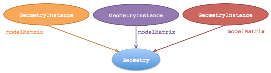
The following example creates one EllipsoidGeometry and two instances. Each instance references the same ellipsoid geometry, but places it using a different modelMatrix resulting in one ellipsoid being on top of the other.
var widget = new Cesium.CesiumWidget('cesiumContainer');
var scene = widget.scene;
var ellipsoid = widget.centralBody.getEllipsoid();

var ellipsoidGeometry = new Cesium.EllipsoidGeometry({
    vertexFormat : Cesium.PerInstanceColorAppearance.VERTEX_FORMAT,
    radii : new Cesium.Cartesian3(300000.0, 200000.0, 150000.0)
});

var cyanEllipsoidInstance = new Cesium.GeometryInstance({
    geometry : ellipsoidGeometry,
    modelMatrix : Cesium.Matrix4.multiplyByTranslation(
        Cesium.Transforms.eastNorthUpToFixedFrame(ellipsoid.cartographicToCartesian(Cesium.Cartographic.fromDegrees(-100.0, 40.0))),
        new Cesium.Cartesian3(0.0, 0.0, 150000.0)
    ),
    attributes : {
        color : Cesium.ColorGeometryInstanceAttribute.fromColor(Cesium.Color.CYAN)
    }
});

var orangeEllipsoidInstance = new Cesium.GeometryInstance({
    geometry : ellipsoidGeometry,
    modelMatrix : Cesium.Matrix4.multiplyByTranslation(
        Cesium.Transforms.eastNorthUpToFixedFrame(ellipsoid.cartographicToCartesian(Cesium.Cartographic.fromDegrees(-100.0, 40.0))),
        new Cesium.Cartesian3(0.0, 0.0, 450000.0)
    ),
    attributes : {
        color : Cesium.ColorGeometryInstanceAttribute.fromColor(Cesium.Color.ORANGE)
    }
});

scene.getPrimitives().add(new Cesium.Primitive({
    geometryInstances : [cyanEllipsoidInstance, orangeEllipsoidInstance],
    appearance : new Cesium.PerInstanceColorAppearance({
        translucent : false,
        closed : true
    })
})); 
TODO: updating per-instance show/color/attribute
Geometry defines structure. The other key property of a primitive, appearance, defines the primitive's shading, i.e., how individual pixels are colored. A primitive can have many geometry instances, but it can only have one appearance. Depending on the type of appearance, an appearance will have a material that defines the bulk of the shading.
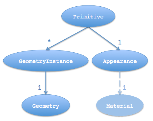
Cesium has the following appearances.
-
MaterialAppearance- An appearance that works with all geometry types and supports materials to describe shading. -
EllipsoidSurfaceAppearance- A version ofMaterialAppearancethat assumes geometry is parallel to the surface of the globe, like a polygon, and uses this assumption to save memory by procedurally computing many vertex attributes. -
PerInstanceColorAppearance- Uses per-instance color to shade each instance. -
DebugAppearance- A debugging aid for visualizing geometry vertex attributes.
Appearances define the full GLSL vertex and fragment shaders that execute on the GPU when the primitive is drawn. We rarely touch these unless we are writing a custom appearance. Appearances also define the full render state, which controls the GPU's state when the primitive is drawn. We can define the render state directly or use higher-level properties like closed and translucent, which the appearance will convert into render state. For example:
// Perhaps for an opaque box that the viewer will not enter.
//  - Backface culled and depth tested.  No blending.

var appearance  = new Cesium.PerInstanceColorAppearance({
  translucent : false,
  closed : true
});

// This appearance is the same as above
var anotherAppearance  = new Cesium.PerInstanceColorAppearance({
  renderState : {
    depthTest : {
      enabled : true
    },
    cull : {
      enabled : true,
      face : Cesium.CullFace.BACK
    }
  }
});
Once an appearance is created, we can't change its renderState property, but we can change its material. Likewise, we can also change a primitive's appearance property.
Most appearances also have flat and faceForward properties, which indirectly control the GLSL shaders.
-
flat- Flat shading. Do not take lighting into account. -
faceForward- When lighting, flip the normal so it is always facing the viewer. The avoids black areas on back-faces, e.g., the inside of a wall.
TODO: screenshots of flat and faceForward
We've already seen that not all appearances work with all geometries. For example, EllipsoidSurfaceAppearance is not appropriate for WallGeometry since a wall is perpendicular to the globe, not parallel.
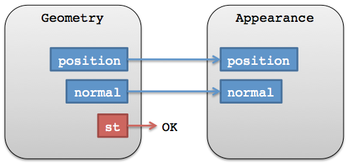
Beyond semantics like this, for an appearance to be compatible with a geometry, they must have matching vertex formats, which means the geometry must have the data that the appearance expects as input. A VertexFormat can be provided when creating a geometry.
We can keep things simple, but inefficient and wasteful, by requesting a geometry compute all vertex attributes, which will make the geometry compatible with all appearances (ignoring per-instance attributes; see below).
var geometry = new Cesium.ExtentGeometry({
  vertexFormat : Cesium.VertexFormat.ALL
  // ...
});

If we are using EllipsoidSurfaceAppearance, for example, we can get away with just requesting positions.
var geometry = new Ceisum.ExtentGeometry({
  vertexFormat : Ceisum.VertexFormat.POSITION_ONLY
  // ...
});
In general, how do we know what vertex format to use for a given appearance? Most appearances have a vertexFormat property or even a VERTEX_FORMAT static constant.
var geometry = new Ceisum.ExtentGeometry({
  vertexFormat : Ceisum.EllipsoidSurfaceAppearance.VERTEX_FORMAT
  // ...
});

var geometry2 = new Ceisum.ExtentGeometry({
  vertexFormat : Ceisum.PerInstanceColorAppearance.VERTEX_FORMAT
  // ...
});

var appearance = new Ceisum.MaterialAppearance(/* ... */);
var geometry3 = new Ceisum.ExtentGeometry({
  vertexFormat : appearance.vertexFormat
  // ...
});
Also, a geometry's vertexFormat determines if it can be combined with another geometry. Two geometries do not have to be the same type; they just need matching vertex formats.
In the reference documentation, see:
For more on materials, see Fabric.
For future plans, see the Geometry and Appearances Roadmap.
If you have questions, post them to the forum.
The following tutorial explains how to add new geometry and appearance types to the Cesium codebase. To follow along, download the latest full version of Cesium, or fork the Cesium repository.
Since geometries and appearances are decoupled, we can add new geometries that are compatible with many appearances and vice-versa. Doing so requires some knowledge of computer graphics and geometry. In this tutorial, we create a simple new Geometry and Appearance. If you develop new geometries or appearances that would be useful to the Cesium community, please consider contributing them.
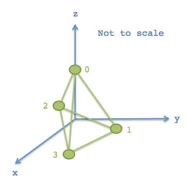
Geometry is a geometry representation that supports indexed or non-indexed triangles, lines, or points. Let's start by making a simple geometry for a tetrahedron, which is a solid composed of four equilateral triangles forming a pyramid. To begin, create the file TetrahedronGeometry.js in the Cesium Source/Core/ directory and add the following code:
/*global define*/
define([
        './Cartesian3',
        './ComponentDatatype',
        './PrimitiveType',
        './BoundingSphere',
        './GeometryAttribute',
        './GeometryAttributes',
        './VertexFormat',
        './Geometry'
    ], function(
        Cartesian3,
        ComponentDatatype,
        PrimitiveType,
        BoundingSphere,
        GeometryAttribute,
        GeometryAttributes,
        VertexFormat,
        Geometry) {
    "use strict";

    var TetrahedronGeometry = function() {
        var negativeRootTwoOverThree = -Math.sqrt(2.0) / 3.0;
        var negativeOneThird = -1.0 / 3.0;
        var rootSixOverThree = Math.sqrt(6.0) / 3.0;

        var positions = new Float64Array(4 * 3);

        // position 0
        positions[0] = 0.0;
        positions[1] = 0.0;
        positions[2] = 1.0;

        // position 1
        positions[3] = 0.0;
        positions[4] = (2.0 * Math.sqrt(2.0)) / 3.0;
        positions[5] = negativeOneThird;

        // position 2
        positions[6] = -rootSixOverThree;
        positions[7] = negativeRootTwoOverThree;
        positions[8] = negativeOneThird;

        // position 3
        positions[9] = rootSixOverThree;
        positions[10] = negativeRootTwoOverThree;
        positions[11] = negativeOneThird;

        var attributes = new GeometryAttributes({
            position : new GeometryAttribute({
                componentDatatype : ComponentDatatype.DOUBLE,
                componentsPerAttribute : 3,
                values : positions
            })
        });

        var indices = new Uint16Array(4 * 3);

        // back triangle
        indices[0] = 0;
        indices[1] = 1;
        indices[2] = 2;

        // left triangle
        indices[3] = 0;
        indices[4] = 2;
        indices[5] = 3;

        // right triangle
        indices[6] = 0;
        indices[7] = 3;
        indices[8] = 1;

        // bottom triangle
        indices[9] = 2;
        indices[10] = 1;
        indices[11] = 3;

        this.attributes = attributes;
        this.indices = indices;
        this.primitiveType = PrimitiveType.TRIANGLES;
        this.boundingSphere = undefined;
    };

    return TetrahedronGeometry;
});
The tetrahedron is made up of four vertices, whose positions lie on the unit sphere. For precision, we always store positions in a Float64Array.
Each of the tetrahedron's four triangles is defined by three indices. Using indices - as opposed to defining three vertices per triangle - allows us to reuse vertices to save memory. For our tetrahedron, each vertex is indexed three times since each vertex has three incident triangles. Indices are stored in a Uint16Array, but can also be stored in a Uint32Array if more than 64K vertices are used.
Tip: Use IndexDatatype.createTypedArray to allocate the right typed array for indices.
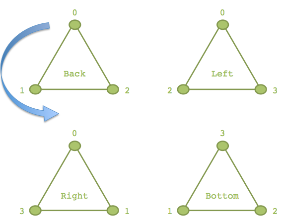
As shown with the blue arrow on the back triangle, the outward-facing side of the triangle is defined by ordering indices in counter-clockwise order. If we wrapped four fingers of our righthand around the back triangle in the orders the indices are defined, 0 - 1 - 2, our thumb points in the direction that is considered outward facing. In Cesium, this counter-clockwise winding order is required.
Our tetrahedron assigns to four public properties, which are required to meet the Geometry interface.
this.attributes = attributes;
this.indices = indices;
this.primitiveType = Cesium.PrimitiveType.TRIANGLES;
this.boundingSphere = undefined;
-
attributes- AGeometryAttributesobject where each property is aGeometryAttribute. Each attribute defines one characteristic of the vertices in the geometry, and data is stored in a typed array. Examples of attributes include positions, normals, and colors. -
indices(optional) - Index data that indexes intoattributes. Using indices allows us to reuse vertices without duplicating them (and avoiding duplication is virtually always a win). For example, our tetrahedron has 4 vertices and each vertex is part of 3 different triangles. Using indices allows us to reuse the same vertex for each triangle instead of creating a copy. -
primitiveType- The primitive that composes the geometry. Most often this isTRIANGLESorLINES, which provide the most flexibility. This determines how the indices (or vertices) are interpreted. For example, whenTRIANGLESis used, every three vertices is interpreted as a triangle. -
boundingSphere(optional) - A sphere that encloses the geometry. This is used to improve drawing performance via culling.
We can improve the performance of drawing our tetrahedron by computing the bounding sphere.
this.boundingSphere = BoundingSphere.fromVertices(positions);BoundingSphere has functions to compute a tight bounding sphere like fromVertices, but in many cases we can use our knowledge of the geometry to quickly create a tighter bounding sphere. Since we know the tetrahedron's vertices lie on the unit sphere, we can just use the unit sphere as the bounding sphere:
this.boundingSphere = new BoundingSphere(new Cartesian3(0.0, 0.0, 0.0), 1.0);Our tetrahedron is centered in its local coordinate system and inscribed in the unit sphere. To visualize it, we need to compute a modelMatrix to position and scale it. In addition, since it only has position attributes, we'll use an appearance with flat shading so normals are not required. First, build the code and run the HTTP server for testing (.\Tools\apache-ant-1.8.2\bin\ant combine runServer). Navigate to http://localhost:8080/Apps/Sandcastle/index.html, your local version of Cesium Sandcastle. Paste the following code in the Sandcastle Hello World demo:
var widget = new Cesium.CesiumWidget('cesiumContainer');
var scene = widget.scene;
var ellipsoid = widget.centralBody.getEllipsoid();
var modelMatrix = Cesium.Matrix4.multiplyByUniformScale(
Cesium.Matrix4.multiplyByTranslation(
Cesium.Transforms.eastNorthUpToFixedFrame(ellipsoid.cartographicToCartesian(
Cesium.Cartographic.fromDegrees(-100.0, 40.0))),
new Cesium.Cartesian3(0.0, 0.0, 200000.0)),
500000.0);
var instance = new Cesium.GeometryInstance({
geometry : new Cesium.TetrahedronGeometry(),
modelMatrix : modelMatrix,
attributes : {
color : Cesium.ColorGeometryInstanceAttribute.fromColor(Cesium.Color.WHITE)
}
});
scene.getPrimitives().add(new Cesium.Primitive({
geometryInstances : instance,
appearance : new Cesium.PerInstanceColorAppearance({
flat : true,
translucent : false
})
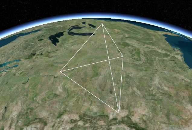
}));Here's our tetrahedron, scaled and positioned, without shading:

Without shading, it is hard to see the surfaces. To view a wireframe, we could change the primitiveType to LINES and change the indices to represent a line segment per unique triangle edge. However, GeometryPipeline is a collection of functions that transform geometries. The function GeometryPipeline.toWireframe transforms a geometry to use the LINES primitive type. Replace the instance declaration with this:
var instance = new Cesium.GeometryInstance({
  geometry : Cesium.GeometryPipeline.toWireframe(new Cesium.TetrahedronGeometry()),
  modelMatrix : modelMatrix,
  attributes : {
    color : Cesium.ColorGeometryInstanceAttribute.fromColor(Cesium.Color.WHITE)
  }
});
Tip: Use GeometryPipeline.toWireframe for debugging to visualize a geometry's primitives.
To use an appearance with shading, the geometry must have a normal attribute. The normal vectors can be computed after the geometry is created using GeometryPipeline.computeNormal. Lets take a look at how the generated normals effect shading. In the Sandcastle example, replace the instance and primitive declarations with the following:
var tetrahedron = Cesium.GeometryPipeline.computeNormal(new Cesium.TetrahedronGeometry());
var instance = new Cesium.GeometryInstance({
    geometry : tetrahedron,
    modelMatrix : modelMatrix,
    attributes : {
        color : Cesium.ColorGeometryInstanceAttribute.fromColor(Cesium.Color.WHITE)
    }
});

scene.getPrimitives().add(new Cesium.Primitive({
    geometryInstances : instance,
    appearance : new Cesium.PerInstanceColorAppearance({
        translucent : false
    })
}));
I'm guessing this is not what you'd expect a tetrahedron with shading to look like. To better understand what's happening, we can visualize the normal vectors with createTangentSpaceDebugPrimitive. Add the following code to the end of the sandcastle exampe:
scene.getPrimitives().add(Cesium.createTangentSpaceDebugPrimitive({
    geometry: tetrahedron,
    modelMatrix: modelMatrix,
    length: 0.2
}));
As you can see, the normal vectors aren't very 'normal' to any of the triangles. Because the vertices are shared by more than one triangle, the normal vectors are the average of the normal to each triangle the vertex composes. To get better shading, we must duplicate each vertex so that the triangles no longer share them.


In TetrahedronGeometry.js, replace the positions and indices with the following:
var positions = new Float64Array(4 * 3 * 3);
// back triangle
positions[0] = 0.0;
positions[1] = 0.0;
positions[2] = 1.0;
positions[3] = 0.0;
positions[4] = (2.0 * Math.sqrt(2.0)) / 3.0;
positions[5] = negativeOneThird;
positions[6] = -rootSixOverThree;
positions[7] = negativeRootTwoOverThree;
positions[8] = negativeOneThird;

// left triangle
positions[9] = 0.0;
positions[10] = 0.0;
positions[11] = 1.0;
positions[12] = -rootSixOverThree;
positions[13] = negativeRootTwoOverThree;
positions[14] = negativeOneThird;
positions[15] = rootSixOverThree;
positions[16] = negativeRootTwoOverThree;
positions[17] = negativeOneThird;

// right triangle
positions[18] = 0.0;
positions[19] = 0.0;
positions[20] = 1.0;
positions[21] = rootSixOverThree;
positions[22] = negativeRootTwoOverThree;
positions[23] = negativeOneThird;
positions[24] = 0.0;
positions[25] = (2.0 * Math.sqrt(2.0)) / 3.0;
positions[26] = negativeOneThird;

// bottom triangle
positions[27] = -rootSixOverThree;
positions[28] = negativeRootTwoOverThree;
positions[29] = negativeOneThird;
positions[30] = 0.0;
positions[31] = (2.0 * Math.sqrt(2.0)) / 3.0;
positions[32] = negativeOneThird;
positions[33] = rootSixOverThree;
positions[34] = negativeRootTwoOverThree;
positions[35] = negativeOneThird;

var indices = new Uint16Array(4 * 3);

// back triangle
indices[0] = 0;
indices[1] = 1;
indices[2] = 2;

// left triangle
indices[3] = 3;
indices[4] = 4;
indices[5] = 5;

// right triangle
indices[6] = 6;
indices[7] = 7;
indices[8] = 8;

// bottom triangle
indices[9] = 9;
indices[10] = 10;
indices[11] = 11;
Now build Cesium, and reload the sandcastle example.

Using a web workers for the geometry types allows the computation to happen asynchronously. The first step is to add createTetrahedronGeometry.js to the Source/Workers/ directory. This will contain a function to instruct the web worker what do to when it is triggered. In this case, we want to create the geometry in the worker. Copy and paste the following code into the createTetrahedronGeometry.js file:
/*global define*/
define([
        '../Core/TetrahedronGeometry',
        '../Scene/PrimitivePipeline',
        './createTaskProcessorWorker'
    ], function(
        TetrahedronGeometry,
        PrimitivePipeline,
        createTaskProcessorWorker) {
    "use strict";

    function createTetrahedronGeometry(parameters, transferableObjects) {
        var geometry = TetrahedronGeometry.createGeometry();
        PrimitivePipeline.transferGeometry(geometry, transferableObjects);

        return {
            geometry : geometry,
            index : parameters.index
        };
    }

    return createTaskProcessorWorker(createTetrahedronGeometry);
});
Now we're going to modify TetrahedronGeometry.js. We don't want the computation of positions and indices to happen until TetrahedronGeometry.computeGeometry is called. Change the current TetrahedronGeometry constructor to:
TetrahedronGeometry.createGeometry = function() {
...
};
This function is going to return a Geometry. Replace the last four lines of the function (this.attributes = attributes;....) with
return new Geometry({
    attributes : attributes,
    indices : indices,
    primitiveType : PrimitiveType.TRIANGLES,
    boundingSphere : new BoundingSphere(new Cartesian3(0.0, 0.0, 0.0), 1.0)
});
The next step is to introduce a new constructor. Add the following code:
var TetrahedronGeometry = function() {
    this._workerName = 'createTetrahedronGeometry';
};TODO: tip for visualizing bounding spheres with command debugging
**TODO: tip for visualizing vectors with **
TODO